Practical guide
Draw an Out-of-Square Room From Measured Corner Distances
Reconstruct a room corner from a baseline and two measured distances, rather than assuming right angles. Follow a complete skew-plan example, reject inconsistent inputs and retain measurement uncertainty.
A rectangular drawing is a hypothesis until the corners agree
Four wall lengths do not generally determine a room’s angles. A skew quadrilateral and a rectangle can have the same pair of opposite side lengths. If you draw right angles merely because the room looks rectangular, a carefully scaled furniture piece may be tested against the wrong shape.
A useful alternative is to locate each relevant corner from its distances to two fixed reference points. In the simple construction here, reference points A and B form a baseline. Two distances locate a corner on either side of that line; the actual side of the room chooses which solution applies. This is an original two-dimensional geometry example, not a measured plan of anyone’s home.
Choose accessible, identifiable finished-surface points and one unit system. Label their location and measurement basis. Do not mix a wall-centre blueprint distance with an inside finished-surface distance. If you cannot locate or measure a point safely and reliably, leave it unresolved and obtain an appropriate measured plan. No risky physical trial or movement of furniture is needed for the calculation.
Derive the corner from two distances to one baseline
Set A=(0,0) and B=(L,0), with L positive. A corner P=(x,y) is at distance rA from A and rB from B. The squared-distance equations are rA²=x²+y² and rB²=(x−L)²+y². Subtracting them eliminates y² and gives 2Lx=rA²−rB²+L².
Thus x=(rA²−rB²+L²)/(2L), followed by y=±√(rA²−x²). All lengths must have the same unit; x and y then have that unit. The plus and minus choices are mirror images across the baseline, not two measurements of the same room. Select the side by the actual plan and point labels.
The construction does not require x to fall between 0 and L. A corner can project beyond either end of the baseline. Rejecting x>L simply because it looks unusual would distort a room that genuinely extends beyond B. Conversely, a negative quantity under the square root is inconsistent with the stated inputs; do not take its absolute value to force a plausible-looking corner.
y = ±√(rA² − x²)
Reconstruct a complete fictional four-corner room
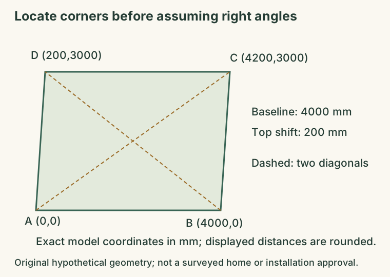
Use a 4000 mm baseline A=(0,0), B=(4000,0). Place both remaining corners on the positive-y side. For C, use exact fictional squared distances rA²=26,640,000 mm² and rB²=9,040,000 mm². Their unrounded lengths are √26,640,000 mm and √9,040,000 mm, displayed approximately as 5161.4 mm and 3006.7 mm.
Substitution gives xC=(26,640,000−9,040,000+16,000,000)/8000=4200 mm. Then yC²=26,640,000−4200²=9,000,000 mm², so yC=3000 mm. C lies 200 mm beyond B’s horizontal coordinate. Those calculations use the exact invented inputs; the displayed rounded lengths are not being presented as accurate field measurements.
For D, take rA²=9,040,000 mm² and rB²=23,440,000 mm². The construction gives xD=200 mm and yD=3000 mm. Join A→B→C→D→A, preserving that physical order. This example is a parallelogram with a 200 mm horizontal shift at the far wall, rather than a 4000×3000 mm rectangle.
Its diagonals AC and BD are approximately 5161.4 mm and 4841.5 mm. A 4000×3000 mm rectangle would instead have two 5000 mm diagonals, although its side lengths would also differ from this skew example. The point is to use consistent corner geometry, not to pick the familiar diagonal because it makes the room drawing simpler.
| Corner | Distance to A, displayed | Distance to B, displayed | Exact model coordinate |
|---|---|---|---|
| C | 5161.4 mm | 3006.7 mm | (4200,3000) mm |
| D | 3006.7 mm | 4841.5 mm | (200,3000) mm |
Check consistency and keep the actual corner order
Two circles with the measured radii must be able to meet. In the nondegenerate case, |rA−rB|<L<rA+rB. Equality produces a collinear point rather than a room corner with a positive perpendicular offset. For example, L=4000 mm and rA=rB=1000 mm cannot form this triangle: the two shorter distances add to only 2000 mm.
Recompute the distances from each derived coordinate to A and B. Keep an independent plan check where one is actually available. The equations recover the stated input geometry; they do not establish that the inputs came from the correct surfaces or a trustworthy measurement.
A polygon also needs the correct order of its boundary points. Joining arbitrary labels can create a crossing outline. For an L-shaped room, mark the recess corners instead of connecting only the four outer extremes. Locate columns and other fixed intrusions separately. Reconstructing four points cannot restore an omitted obstruction.
A more detailed formula does not create more accurate measurements
A rounded input can shift the reconstructed point. Retain the original dimensions, their resolution and the basis of any uncertainty ranges. Do not label a result accurate to 0.1 mm merely because a calculator displays a decimal. The exact squared lengths above are teaching inputs chosen to yield checkable coordinates, not a claim that a tape measure supplied them.
NIST defines exact relationships between length units, including 25.4 mm per standard inch. Convert before combining inputs, but keep measurement uncertainty separate from that exact factor. When the relevant distances are unresolved, treat the room corner as unresolved. Near-collinear geometry is particularly sensitive: a small change can substantially alter the perpendicular offset or remove the circle intersection.
Finally, scale the reconstructed outline consistently and add full furniture, actual openings and their operation. USFA recommends drawing doors and windows and keeping them unblocked; actual building and local requirements still apply. A two-dimensional corner calculation is neither an escape-plan certification nor approval of furniture height, installation or access.
Download the blank planning record
Case 1
C is reconstructed at x=4200 mm while the baseline ends at x=4000 mm. Must that coordinate be rejected?
Show answer and explanation for case 1
No.
A corner may project beyond the baseline endpoint. Check the stated distances and actual side and point identity rather than forcing a rectangular outline.
Case 2
Can a 4000 mm baseline and two 1000 mm corner distances form this triangle?
Show answer and explanation for case 2
No.
The two shorter distances sum to 2000 mm, below the 4000 mm baseline. These inputs have no circle-intersection solution.
Case 3
The squared-distance equations return y=±3000 mm. Do both signs describe the same side of the baseline?
Show answer and explanation for case 3
No.
They are mirror-image locations. The actual room orientation and corner labels determine which side applies.
Sources and further reading
- NIST: SI Units – LengthMetric unit relationships and exact 25.4 mm per inch; updated 19 September 2025. Units do not certify a measured range or furniture clearance.
- USFA: Home Fire Escape PlansMap actual doors and windows and keep them unblocked; reviewed 10 April 2025. Follow the actual building and local arrangements; no universal passage width inferred.