Practical guide
Furniture Fits at Both Ends: Check the Entire Moving Path
A frame can fit at the start and finish yet collide halfway along a move. Compare a failed straight translation with two complete swept footprints, keeping actual handling and installation requirements separate.
A fitted starting position and a fitted destination are two snapshots
Furniture may fit where it starts and where you want it, yet collide with the room halfway along the proposed move. A final footprint cannot approve a continuous route. For a stated movement, check the whole footprint at every stage, including protrusions and anything that changes shape.
This guide constructs an original fixed-orientation translation example. Translation moves every point by the same displacement; it does not rotate, fold or tilt the frame. An actual delivery can involve different motions, height restrictions, handling space and product instructions. Those conditions are outside this simple calculation and cannot be replaced by a successful floor-plan drawing.
Use the measured occupied room, not a rectangular envelope around a recess. Mark actual openings, fixed furniture and obstacles at the relevant height. Use the full outside outline of the moving object. Do not substitute a mattress dimension or ignore a handle just because it does not appear on a catalogue thumbnail.
Specify the shape, reference point and continuous movement
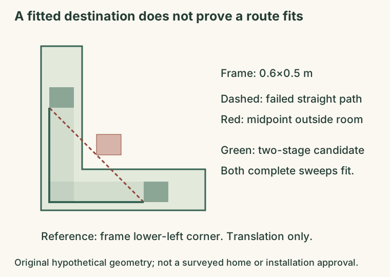
Our wholly fictional room is the L-shaped union of a 4×1 m horizontal arm and a 1×4 m vertical arm. The boundary runs through (0,0), (4,0), (4,1), (1,1), (1,4), (0,4), in metres. A 0.6×0.5 m rectangular frame remains axis-aligned throughout the example.
Use the frame’s lower-left corner as its reference point. At the start it is (2.5,0.2), so the full rectangle occupies x=2.5–3.1 and y=0.2–0.7. At the finish the reference is (0.2,2.5), occupying x=0.2–0.8 and y=2.5–3.0. Both complete rectangles lie inside one arm of the room.
Now prescribe a straight translation between those reference points. At parameter t from 0 to 1, the reference coordinates are x=2.5−2.3t and y=0.2+2.3t. Every frame point receives that same translation. This is a specified path to test, not an instruction to move a real heavy object diagonally through a home.
Reject the straight path at its midpoint
At t=0.5 the lower-left corner is (1.35,1.35). The full frame occupies x=1.35–1.95 and y=1.35–1.85. Every point in that rectangle has both coordinates greater than 1 m, placing it inside the room’s missing upper-right part. The midpoint frame is outside the occupied floor.
One failed intermediate position is enough to reject this prescribed path. Passing a finite collection of positions is not generally enough to accept a continuous path: a collision can occur between sampled positions. The question is the union of all occupied frame positions, often called its swept footprint.
Keep the meaning of a collision explicit. Here it means the hypothetical frame enters space outside the room outline. In another plan it may mean overlap with a fixed obstacle. Merely overlapping two alternative drawings of the same moving frame is not an obstacle collision; those drawings show different times.
| State | Reference point, m | Full x range, m | Full y range, m | Room containment |
|---|---|---|---|---|
| Start | (2.5,0.2) | 2.5–3.1 | 0.2–0.7 | Inside horizontal arm |
| Midpoint | (1.35,1.35) | 1.35–1.95 | 1.35–1.85 | Outside room |
| Finish | (0.2,2.5) | 0.2–0.8 | 2.5–3.0 | Inside vertical arm |
Check a two-stage alternative over its entire extent
A different mathematical path goes first from reference (2.5,0.2) to (0.2,0.2), then from (0.2,0.2) to (0.2,2.5). Keep the same 0.6×0.5 m frame and orientation. This alternative changes the route, not the furniture size.
During the first, purely horizontal stage, the union of all occupied rectangles is exactly x=0.2–3.1, y=0.2–0.7. Its entire y range lies below 1 m and its x range lies within 0–4 m, so the complete sweep is contained in the horizontal arm. This proof covers the continuous movement, not only the endpoints.
During the second, purely vertical stage, the complete union is x=0.2–0.8, y=0.2–3.0. Its entire x range lies below 1 m and its y range within 0–4 m, so that sweep is inside the vertical arm. The junction frame is included in both stages. Both sweeps therefore pass isolated floor-containment in the stated empty room.
These simple sweeps are rectangles because the hypothetical frame is axis-aligned and each stage is parallel to one axis. A diagonal translation, rotation or nonrectangular object can produce another swept shape. Do not extend this rectangle formula to an unspecified movement and call it verified.
A passing mathematical sweep still leaves actual move requirements
No person, doorway hardware, grip, furniture leg, lifting motion, ceiling, stair or installed object is represented in this empty L-room model. A passing sweep does not show that people can execute the move, that the frame fits through the entrance or that a real product can be handled this way. Obtain the actual configuration’s instructions and appropriate practical assistance where needed.
Final orientation also differs from rotation in place. An object that fits at two angles may require more room at intermediate angles. Our rotated-footprint guide calculates room-axis extents at several orientations; actual rotation still needs its position, obstacles and continuous swept outline. A folding bed likewise needs its changing shape and operating instructions, not this constant rectangle.
USFA recommends showing actual doors and windows and keeping them unblocked. Retain building arrangements and applicable local requirements. Nothing in the 0.2 m drawing offsets establishes an approved passage, working clearance or escape route.
Keep original dimensions and their measurement basis. NIST’s exact unit factor, 25.4 mm per inch, makes unit conversion consistent but cannot settle an uncertain outline. If the path depends on an unknown obstruction or dimension, leave it unresolved. Use the geometry to identify a rejected route or a candidate that needs further checks, rather than attempting to force the object through.
Download the blank planning record
Case 1
The start and finish rectangles are inside. Does this verify the straight translation?
Show answer and explanation for case 1
No.
At its midpoint the full frame lies at x=1.35–1.95, y=1.35–1.85 m, outside the stated L-shaped floor.
Case 2
Why do the two axis-aligned alternative stages pass this empty-room containment check?
Show answer and explanation for case 2
Each complete sweep is inside one rectangular arm.
The first occupies x=0.2–3.1,y=0.2–0.7 m; the second x=0.2–0.8,y=0.2–3.0 m. The whole unions, not just samples, are contained.
Case 3
Do those two sweeps prove a real furniture delivery can be performed?
Show answer and explanation for case 3
No.
The model omits handling, people, height, hardware, actual product instructions and other obstructions. It verifies only the specified isolated two-dimensional geometry.
Sources and further reading
- NIST: SI Units – LengthMetric unit relationships and exact 25.4 mm per inch; updated 19 September 2025. Units do not certify a measured range or furniture clearance.
- USFA: Home Fire Escape PlansMap actual doors and windows and keep them unblocked; reviewed 10 April 2025. Follow the actual building and local arrangements; no universal passage width inferred.